This is BCC's unofficial EVC Truck repository, where all of the files for instrumentation on the truck are stored.

arduino-librariescontains a couple of the library files used for the Arduino Mega. This is just for reference. Honestly, this might not even be necessary at this point.datacontains the data files of our test runs.docscontains important documents or manuals.i2c-gps-programscontains code for the Arduino Mega and UNO to display text on the LCD (using the I2C communication protocol) while getting GPS data (which uses UART serial).imgscontains images that are displayed on this document.megacontains code for the Arduino Mega.canbus123is the most recent program as of summer 2024 for the truck.
test-programscontains basic programs to demonstrate the basic functionality of the hardware.
- The GPS uses the UART serial communication protocol, and the LCD uses I2C.
- The proto shield is used to help with wire management.

- Electrocookie Mega R3 Proto Shield
- Arduino Mega
- SparkFun CAN-BUS Shield
- SparkFun 20x4 SerLCD - RGB Backlight (Qwiic)
- SparkFun GPS Receiver EM-506
- SparkFun Bi-Directional Logic Level Converter
- Breadboard
- Jumper wires
- Micro Center 128GB microSD Card
Plug in the 5-wire connection to the GPS module and to the GPS port on the CAN-BUS Shield. The second and the third wire should be stripped and have male ends soldered onto them, which is shown in the image below:

The two wires should be connected to the appropriate pins:
| GPS Module | Proto Shield (or Mega) |
|---|---|
| Third (middle) wire | Pin 14 |
| Second wire | Pin 15 |
If the prototyping shield isn't being used, the following are the pins you'd connect on the CAN-BUS and the Mega:
| CAN-BUS | Mega |
|---|---|
| 10 | 53 |
| 13 | 52 |
| 11 | 51 |
| 12 | 50 |
If the prototyping shield is being used, the following are the pins you'd connect with female-to-female jumper wires:
| Proto Shield | Proto Shield |
|---|---|
| 10 | 53 |
| 13 | 52 |
| 11 | 51 |
| 12 | 50 |

Reference this hookup guide in general. To hook up the LCD for I2C, see this part of the hookup guide. Here's the diagram. For some reason, the diagram doesn't include the connections for LCD GND and RAW, so we guessed those.
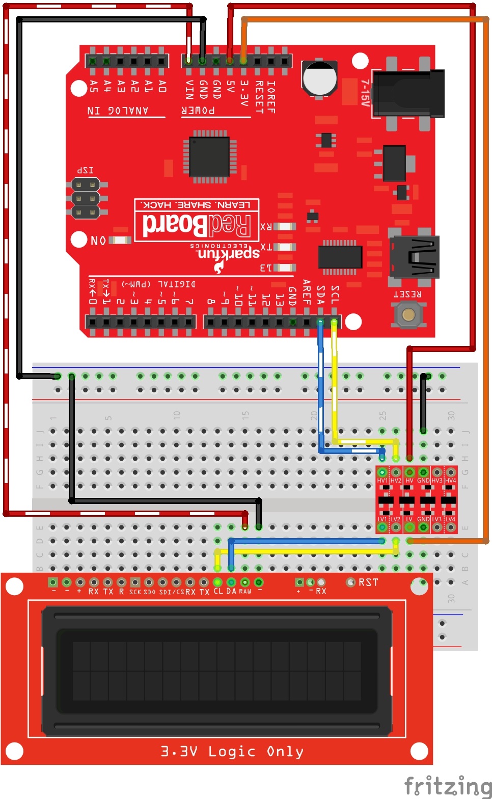
| LCD | Breadboard | CAN-BUS |
|---|---|---|
| GND | A27 | |
| RAW | A15 | |
| SDA | D30 (LV1 on the Logic Level Converter) | |
| SCL | D29 (LV2) | |
| E16 to -2 (from top right) | ||
| D28 (LV) | 3.3v | |
| H28 (HV) | 5v | |
| -1 (top right) | GND | |
| E15 | VIN | |
| H30 (HV1) | SDA | |
| H29 (HV2) | SCL | |
| J27 to -27 (from the right) |
Orient the Logic Level Converter as shown in the image below:

| Metric | Working on Display? | Data is From |
|---|---|---|
| Speed (mph) | Y | GPS |
| RPM | N | Motor controller |
| Battery temperature (C) | Y | BMS |
| Motor controller temperature (C) | N | Motor controller |
| Pack current | Y | BMS |
| Pack voltage | Y | BMS |
| Lowest cell voltage | Y | BMS |
| Lowest cell voltage ID | Y | BMS |
| Kilowatt-hour | Y | BMS |
| Trip (miles) | Y | GPS |
| Time | - | - |
| Latitude/Longitude | - | GPS |
| Altitude (meters) | - | GPS |
| Course (degrees) | - | GPS |
| MPGe | - | BMS |
| Power | - | BMS |
- (17, 1) is the lowest cell voltage ID
- (14, 2) is the lowest cell voltage
| 0 | 1 | 2 | 3 | 4 | 5 | 6 | 7 | 8 | 9 | 10 | 11 | 12 | 13 | 14 | 15 | 16 | 17 | 18 | 19 | |
|---|---|---|---|---|---|---|---|---|---|---|---|---|---|---|---|---|---|---|---|---|
| 0 | x | x | . | x | x | M | P | H | R | P | M | : | x | x | x | x | ||||
| 1 | B | T | : | x | x | x | C | M | C | : | x | x | x | C | # | x | x | |||
| 2 | x | x | x | A | x | x | x | . | x | V | x | . | x | x | x | V | ||||
| 3 | x | x | x | . | x | K | W | H | T | R | I | P | : | x | x | x | . | x |

- In the Arduino code, make sure the baud rates are the same as the BMS via
CANSPEED_125. - In order to retrieve metrics from the BMS, the BMS must be set up with the appropriate parameters under a message identifier. Keep in mind certain parameters take up 2 bytes instead of 1. Within the Arduino code,
ifstatements catch messages on the CAN bus protocol. By accessing the appropriate byte from the message identifier, we can retrieve the metric we need from the BMS.- Take a look at this
ifstatement:if (message.id == 0x123) { int CDEC = 0; for (int i = 0; i < 2; i++) { // (1) int MDATA = (message.data[i]); CDEC = CDEC + (MDATA*(pow(256, 1-i))); } lcd.setCursor(0,1); lcd.print("BT:"); lcd.print(message.data[3],DEC); // (2) lcd.print("C"); lcd.setCursor(17,1); lcd.print("#"); lcd.print(message.data[2],DEC); // (3) lcd.setCursor(13,2); lcd.print((float)CDEC/10000,3); // (4) lcd.print("v"); }
- (1) Gets the low cell voltage by checking bytes 0 and 1.
- (2) Displays the highest battery temperature.
- (3) Displays the low cell voltage ID.
- (4) Displays the low cell voltage from (1).
- Take a look at this
- You'll see some
forstatements that iterate on the same initialization value. This is intentional. Apparently it gets rid of leading zeroes. - Check the editing-canbus-messages document under
docsfor more information.
These can be modified on the BMS software.
| 0x03B | Byte | Metric |
|---|---|---|
| 0 | Pack current | |
| 1 | ||
| 2 | Pack inst voltage | |
| 3 | ||
| 4 | ||
| 5 | ||
| 6 | ||
| 7 |
| 0x3CB | Byte | Metric |
|---|---|---|
| 0 | Pack DCL | |
| 1 | Pack CCL | |
| 2 | ||
| 3 | Simulated SOC | |
| 4 | High temperature | |
| 5 | Low temperature | |
| 6 | ||
| 7 |
| 0x6B0 | Byte | Metric |
|---|---|---|
| 0 | ||
| 1 | Pack SOC | |
| 2 | Pack resistance | |
| 3 | ||
| 4 | Pack open voltage | |
| 5 | ||
| 6 | Pack amphouts | |
| 7 |
| 0x123 | Byte | Metric |
|---|---|---|
| 0 | Low cell voltage | |
| 1 | ||
| 2 | Low cell voltage ID | |
| 3 | High temperature (battery) | |
| 4 | ||
| 5 | ||
| 6 | ||
| 7 |
- Get RPM and motor controller temperature from the motor controller to display on LCD
- Ensure that the data printed to the SD card is formatted properly
- Radio or music player capabilities