Built from furniture scrap destined for bonfire. Painted with leftover wall paint. Zero budget. Zero special tools.
This sidestick was hand-carved from wooden furniture scraps using large carpentry tools — the same ones used to build beds and wardrobes. The enclosure was painted with leftover grey and black house paint. No 3D printer. No CNC. No fresh materials. Every cut, every curve, every hole was made by hand in a carpenter's workshop.
The electronics inside are a $2 STM32 Blue Pill running custom USB HID firmware — plug it into any Windows PC and it shows up as a native joystick. No drivers. No vJoy. No software installation. Just plug and fly.
Real engineering is not about having the best tools. It's about solving problems with what's available.
| Video | Description |
|---|---|
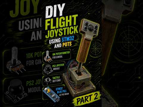 |
HOTAS in action — gameplay short |
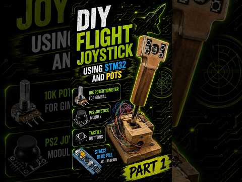 |
Build process short |
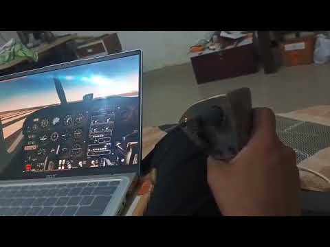 |
Working in FlightGear flight simulator |
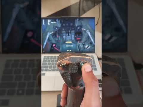 |
Working in War Thunder combat flight sim |
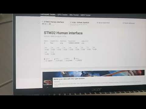 |
All 4 axes and 10 buttons verified |
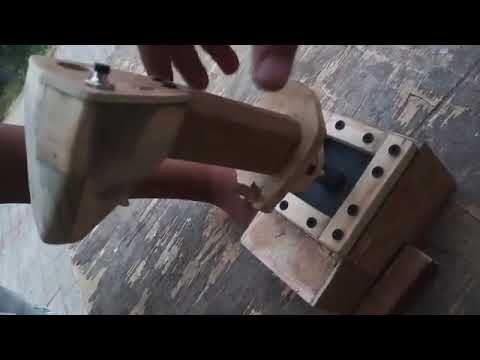 |
Raw wood carving and construction |
| Photo | Description |
|---|---|
 |
Finished sidestick — grey/black leftover furniture paint |
 |
Front perspective showing ergonomic grip angle |
 |
Side profile — pinky hook and trigger guard visible |
 |
Blue Pill STM32 and wiring inside the base |
 |
Button and switch wiring closeup |
 |
Before paint — hand-carved wooden grip |
 |
Blue Pill mounted on zero board in base |
| Property | Value |
|---|---|
| MCU | STM32F103C8T6 (Blue Pill) — $2 |
| Enclosure | Hand-carved furniture scrap wood |
| Paint | Leftover grey/black house paint |
| Firmware | STM32 HAL (CubeIDE) |
| USB | Native HID joystick — no vJoy, no drivers |
| Analog Axes | 4 (2 gimbal + 2 ministick) |
| Digital Buttons | 10 |
| HID Report | 10 bytes |
| Polling Rate | 100 Hz |
| Total Cost | ~$5 (salvaged materials) |
Sidestick style — inspired by F-35, Rafale, Typhoon real aircraft grips.
- Grip — Carved from furniture scrap wood using large hand tools
- Pinky hook — Bottom curve for grip security during intense maneuvers
- Trigger guard — Index finger rest with single stage trigger
- Thumb platform — Top surface with ministick and button layout
- Hat switch housing — M-seal (epoxy putty) molded into cross pattern for 4-directional hat
- Full grip painted grey and black using leftover house paint
- Multiple coats for durability
- Brush-applied — no spray equipment
- STM32 Blue Pill — from old project inventory
- PS2 joystick module — from spare parts box
- Potentiometers — 10k, reused from previous builds
- Tactile buttons — standard 6mm, bulk purchased
- Type-C breakout — spare module from drawer
- Berg strip connectors — cut from longer strips
- Zero board — for mounting Blue Pill in base
- Blue Pill mounted on zero board in base — pull out and reuse in other projects
- Berg strip connector interface — handle wires plug into base
- Same STM32 can be flashed with different firmware and reinserted
- Base designed for easy wire management
| STM32 Pin | ADC Channel | Component | Calibration |
|---|---|---|---|
| PA0 | IN0 | 10k potentiometer — Gimbal X | min=1450, max=2995 |
| PA1 | IN1 | 10k potentiometer — Gimbal Y | min=770, max=1950 |
| PA6 | IN6 | PS2 thumb ministick X | Raw (no calibration) |
| PA7 | IN7 | PS2 thumb ministick Y | Raw (no calibration) |
| STM32 Pin | ADC Channel | Planned Use |
|---|---|---|
| PA2 | IN2 | Rudder yaw |
| PA3 | IN3 | Left pedal |
| PA4 | IN4 | Right pedal |
| PA5 | IN5 | Steering wheel |
| STM32 Pin | HID Bit | Button | Location |
|---|---|---|---|
| PB0 | Bit 0 | PS2 ministick click | Thumb platform |
| PB3 | Bit 1 | Trigger | Index finger |
| PB4 | Bit 2 | Pinky button | Side of grip |
| PB5 | Bit 3 | Red action button | Thumb side |
| PB6 | Bit 4 | Hat switch up | Thumb platform (M-seal) |
| PB7 | Bit 5 | Hat switch down | Thumb platform (M-seal) |
| PB8 | Bit 6 | Hat switch left | Thumb platform (M-seal) |
| PB9 | Bit 7 | Hat switch right | Thumb platform (M-seal) |
| PB11 | Bit 8 | Up button | Thumb platform |
| PB12 | Bit 9 | Down button | Thumb platform |
| STM32 Pin | Function |
|---|---|
| PA11 | USB D- (Type-C breakout) |
| PA12 | USB D+ (Type-C breakout) |
| PA13 | SWDIO (ST-Link V2) |
| PA14 | SWCLK (ST-Link V2) |
| Property | Value |
|---|---|
| USB Version | 2.0 |
| VID | 0x0483 (STMicroelectronics) |
| PID | 0x5723 |
| Max Packet Size | 64 bytes |
| HID Report Size | 10 bytes |
| Polling Interval | 10 ms |
Note: Onboard micro USB bypassed — data lines faulty on clone board. Type-C breakout module wired directly to PA11, PA12. Fixed USB cable on base panel.
Byte 0-1:  Analog Hat X    (16-bit LE, 0-4095, center ~1500)
Byte 2-3:  X Axis          (16-bit LE, 0-4095, calibrated)
Byte 4-5:  Y Axis          (16-bit LE, 0-4095, calibrated)
Byte 6-7:  Z Axis          (16-bit LE, 0-4095, raw)
Byte 8-9:  Rx Axis         (16-bit LE, 0-4095, raw)
Byte 10:   Buttons [0:7]   (8 bits, active-high)
Byte 11:   Buttons [8:9]   (2 bits + 6 padding)
- Framework: STM32 HAL (CubeIDE)
- USB: Native HID joystick — no vJoy, no drivers needed
- ADC: Software channel switching, 12-bit resolution
- Buttons: GPIO with internal pull-up, active-low
- Calibration: Per-axis min/max mapping in firmware
- Axis inversion: Handled in firmware per axis
| Axis | Pin | Min | Max | Inverted |
|---|---|---|---|---|
| Gimbal X | PA0 | 1450 | 2995 | No |
| Gimbal Y | PA1 | 770 | 1950 | Yes |
- ST-Link V2 via SWD — no BOOT0 jumper changes needed
- STM32CubeIDE + HAL framework
- Custom USB HID descriptor in
usbd_hid.c
- Windows Device Manager — shows as "STM32 Human Interface"
- joy.cpl — all axes and buttons confirmed
- Gamepad tester online
- FlightGear flight simulator
- War Thunder
HOTAS_Joystick/
├── Core/
│   ├── Inc/          # Header files
│   └── Src/          # Main firmware (main.c)
├── USB_DEVICE/       # USB HID stack
├── Drivers/          # STM32 HAL drivers
├── Middlewares/      # USB middleware
├── firmware/         # Compiled .elf/.bin (future)
├── media/            # Photos and videos
├── docs/             # Additional documentation
├── HOTAS_Joystick.ioc  # CubeMX project config
└── README.md
- V2 — Refined grip, modular handle with berg connector, same gimbal reused
- Rudder pedals — PA2, PA3, PA4 already reserved
- Steering wheel expansion — PA5 reserved
- Drone GCS mode — UART output planned in future firmware
This project proves a fully functional USB HID joystick can be built from workshop scrap, leftover paint, and determination. Every component was salvaged, borrowed, or repurposed. The only investment was time and creativity.
If you have hands and a problem to solve, you already have everything you need.
MIT License — Use freely, build your own, share what you make.