


This project turns an 8x32 WS2812B RGB LED matrix into a compact, colourful desktop clock that is useful at a glance and fun to interact with. Behind its simple clock face is a complete miniature information display: a calendar, weekday marker, temperature, humidity, atmospheric pressure, selectable colours, adjustable brightness, smooth transitions, and an automatic screen carousel.
The clock is built around an Arduino Pro Mini and deliberately keeps the user interface physical and immediate. There is no phone application, account, or network connection to configure. Three buttons provide access to every feature, while a battery-backed DS3231 keeps time when the main supply is disconnected. A BME280 adds live environmental readings, and the 256 individually addressable LEDs give each screen its own bright, distinctive character.
Timekeeping is designed around the RTC rather than a software counter. The DS3231 stores standard time and remains the single source of truth; the firmware adds the European daylight-saving offset only when creating local civil time for the display. When the user sets the clock, the entered value is understood to be the local time already visible on an ordinary clock. The firmware automatically removes the DST hour before saving it to the RTC, then reads the value back to verify the write.
The repository also includes a complete Arduino Nano-based Wokwi simulation, custom simulated DS3231 and BME280 devices, automated display captures, and separate PlatformIO targets for simulation and physical hardware. This makes it possible to explore the interface and develop most display behaviour before assembling the real clock.
- Custom 8x32 clock face with a calendar tile,
HH:MM, blinking colon, and weekday indicator - Date, temperature, humidity, and pressure screens
- Setup for time, date, 12/24-hour format, and brightness without recompiling
- DS3231 battery-backed timekeeping with verified setup writes
- Automatic European DST conversion between RTC standard time and local time
- BME280 automatic address detection at
0x76or0x77 - Smooth 16-colour font palette selected with the leftmost button
- Debounced short press, long press, and held-button repeat
- Runtime carousel with 5/7-second timing, orange/red mode indicators, and a pull-down transition
- Boot and screen-transition animations
- PlatformIO release and Wokwi build environments
- Release-only upload workflow that cannot accidentally upload the Wokwi target
At startup, the firmware configures the buttons and initializes the RTC, environmental sensor, FastLED display, and application state machine. The non-blocking main loop polls the controls, refreshes the RTC every second, updates the BME280 cache every five seconds, selects the current screen, draws into a 256-element FastLED buffer, and sends the completed frame to the matrix.
The exception is scrolling text and short animations, which deliberately use brief delays while their frames play. The clock screen maps logical (x,y) pixels to the physical LED order and uses compact custom glyphs so a calendar tile and time fit in only eight rows. Normal hardware defaults to column-major serpentine wiring; Wokwi uses progressive row-major wiring.
| Qty | Part | Important details |
|---|---|---|
| 1 | Arduino Pro Mini | ATmega328P, 5 V logic, 16 MHz; PlatformIO board pro16MHzatmega328 |
| 1 | WS2812B LED matrix | 8 rows x 32 columns, 256 individually addressable RGB LEDs, GRB order |
| 1 | DS3231 RTC module | I2C address 0x68; fit a compatible backup coin cell |
| 1 | BME280 breakout | Temperature, humidity, and pressure; I2C address 0x76 or 0x77 |
| 3 | Normally-open momentary buttons | Connected between an input and GND; firmware enables internal pull-ups |
| 1 | Regulated 5 V / 4 A supply | Match the supply and firmware current limit to the finished clock |
| 1 | 1000 uF electrolytic capacitor | Across matrix 5 V and GND, close to the panel; observe polarity |
| 1 | 330-470 ohm resistor | In series between Pro Mini D6 and matrix DIN, close to the matrix |
| optional | 4.7 kohm resistors | SDA/SCL pull-ups if the breakout boards do not already provide them |
The release firmware, src/config.h, and the Wokwi diagram all use the same
signal assignments. The Nano pins in the simulation are electrically equivalent
to the Pro Mini pins used by the physical build.
| Physical Pro Mini | Wokwi Nano | Connects to | Wiring notes |
|---|---|---|---|
| D3 | D3 | MODE button | Other button terminal to GND; active low with internal pull-up; INT1-capable |
| D4 | D4 | UP button | Other button terminal to GND; active low with internal pull-up |
| D5 | D5 | DOWN button | Other button terminal to GND; active low with internal pull-up |
| D6 | D6 | 330-470 ohm resistor, then matrix DIN | Connect to DIN, not DOUT |
| A4 / SDA | A4 | DS3231 SDA and BME280 SDA/SDI | Shared I2C data bus |
| A5 / SCL | A5 | DS3231 SCL and BME280 SCL/SCK | Shared I2C clock bus |
| VCC / 5 V | 5 V | DS3231 and suitable BME280 breakout power | Confirm the breakout accepts 5 V; a bare BME280 does not |
| External regulated 5 V | 5 V | Matrix VDD | Power the matrix directly from the 4 A supply, not through the Pro Mini |
| GND | GND | Pro Mini, matrix, RTC, BME280, buttons, and external supply | Every component must share the same ground reference |
On the custom Wokwi BME280, CS is tied to VDD for I2C operation and SDO
is tied to GND to select address 0x76. The firmware also probes 0x77 for
breakout boards wired with SDO high.
Do not power a 256-pixel panel through the Pro Mini regulator or USB-to-serial adapter. Feed the matrix directly from a regulated 5 V supply and join that supply's ground to Pro Mini GND. Inject power at more than one point if wiring or panel voltage drop becomes visible.
A WS2812B can approach 60 mA at full-brightness white, so an unconstrained
256-pixel panel has a theoretical worst case near 15.4 A. The physical 1-10
brightness scale maps to FastLED values 2-64 and starts at level 9. FastLED also
enforces an estimated 4000 mA ceiling. These are software safeguards, not a
replacement for suitable wiring, power injection, connectors, fusing,
decoupling, and verification with the actual panel and supply. Reduce
LED_MAX_MILLIAMPS if the controller and LEDs share a supply that cannot
provide additional margin.
Many BME280 breakouts contain a 3.3 V regulator and level shifting and accept 5 V; a bare BME280 does not. Verify the markings and datasheet for your particular module. Likewise, confirm whether the RTC and sensor boards already include I2C pull-ups. DS3231 modules vary in their coin-cell charging circuit: never install a non-rechargeable cell in a module that actively charges it.
Physical hardware defaults to a vertical, column-major serpentine arrangement:
- LED 0 is at the bottom-right;
- the chain first rises through the rightmost column;
- it then moves one column left and alternates downward/upward while progressing from right to left.
Set MATRIX_LAYOUT in src/config.h or through a build flag if your panel is progressive row-major or serpentine row-major. A wrong selection produces mirrored, striped, or scrambled graphics without harming the LEDs.
All clock functions are available from three buttons:
- MODE — short press: select the next font colour from the 16-colour palette.
- MODE — long press: enter setup. While in setup, a long press saves all settings immediately and returns to the clock.
- UP — short press: move backwards through the normal display screens.
- DOWN — short press: move forwards through the normal display screens.
- UP or DOWN — long press: cycle the automatic carousel through off, five-second dwell, seven-second dwell, and off again.
- MODE — short press during setup: accept the current field and advance to the next one.
- UP during setup: increase the selected value; keep holding to repeat.
- DOWN during setup: decrease the selected value; keep holding to repeat.
The carousel cycles through clock, temperature, humidity, and pressure; it deliberately skips the date. A bottom-right dot flashes orange for the 5-second mode and red for the 7-second mode. Entering setup disables it. Stopping the carousel leaves the currently displayed screen selected and removes the indicator.
Setup fields appear in this order:
- Hour
- Minute
- Day
- Month
- Year
- 12/24-hour format
- Brightness level from 1 to 10
The selected field flashes, and any button activity restarts the seven-second inactivity timer. Completing the final field, holding MODE, or allowing the setup timer to expire saves the buffered date/time, display format, and brightness. Every one of these setup exit paths writes the entered date and time to the RTC. Seconds are reset to zero. Day values are constrained to the selected month and year, including leap years, and brightness changes are previewed immediately while editing.
The 1-10 brightness value is the stable user-facing setting; the firmware maps it to the target-specific FastLED range. Physical hardware uses values 2-64, while Wokwi uses 26-255 so the simulator can show colour gradients clearly. Both start at level 9.
The DS3231 is the authoritative clock and continues counting from its backup
battery while the controller is unpowered. The firmware does not maintain an
independent millis()-based wall clock that could slowly drift away from the
RTC. millis() is used only to schedule the next poll; the displayed seconds,
minutes, date, and weekday always come from the most recent DS3231 reading.
To keep display rendering fast and avoid unnecessary I2C traffic, the application keeps a local civil-time cache. Every screen reads this cache rather than accessing the RTC directly. The DS3231 is accessed at these times:
| When | DS3231 access | Purpose |
|---|---|---|
| Startup | Probe the device and read its power-loss flag | Confirm that the RTC is available and determine whether its stored time can be trusted |
| Startup after a power-loss indication | Write 2026-01-01 00:00:00 standard time |
Establish a known baseline for a new or discharged RTC; the user must then set the correct local time |
| Startup after initialization | Read once immediately | Populate the cache before normal application operation |
| Normal operation | Read every RTC_POLL_MS (1000 ms) |
Refresh all displayed time/date fields from the hardware time source and recalculate DST |
| Saving setup changes | Write the complete date and time, then read immediately | Store the edited value and verify the hardware registers; a read-back equal to the requested second or the following second is accepted |
| Immediately after a setup write | Read once more through the normal cache update | Make the newly saved local time visible without waiting for the next periodic poll |
If the DS3231 cannot be initialized, the RTC cache remains invalid and no
further periodic reads or setup writes are attempted. The application does not
synthesize elapsed wall time from millis(); accuracy therefore never depends
on controller loop timing.
The RTC always stores standard time. The application exposes local civil time:
- During setup, the hour entered by the user is assumed to include DST already.
- The firmware calculates European DST from the entered local date.
- If DST is active, it subtracts one hour from the complete date/time before writing to the RTC. This also handles crossing into the previous day.
- The RTC is read back immediately. A matching value, allowing for one elapsed second, verifies that the setup write succeeded.
- On every one-second RTC poll, DST is recalculated and the local cache is refreshed. This guarantees that a change of RTC day is noticed immediately.
The current rule is date-based: DST is active from the last Sunday in March
through the day before the last Sunday in October. Consequently, the offset
changes when the RTC date enters the relevant transition day at 00:00
standard time. Exact statutory hour-based switching at 01:00 UTC is not
implemented.
| Path | Purpose |
|---|---|
src/main.cpp |
Arduino entry point and subsystem initialization |
src/config.h |
Pins, timings, colors, layouts, and feature flags |
src/app/clock_app.* |
Screen and setup state machine |
src/display/display_manager.* |
FastLED buffer, coordinate mapping, fonts, clock UI, scrolling, animations |
src/display/font3x5.h |
Compact numeric 3x5 bitmap font stored in flash |
src/input/button_manager.* |
Debouncing, short/long presses, and repeat events |
src/sensors/rtc_manager.* |
RTClib DS3231 wrapper and cached date/time |
src/sensors/bme_manager.* |
BME280 discovery, configuration, validation, and cached readings |
diagram.json, wokwi.toml |
Wokwi circuit and firmware configuration |
chips/ |
Custom Wokwi DS3231 and BME280 chip models |
scripts/build_wokwi.py |
Builds Wokwi after a normal release build, but skips it for uploads |
wokwi-icons.test.yaml |
Automated simulator navigation and environmental-icon screenshots |
The BME280 is polled every five seconds on hardware. It runs in normal mode
with x2 temperature, x16 pressure, and x1 humidity oversampling, x16 IIR
filtering, and 500 ms standby. If the DS3231 reports loss of power, firmware
initializes it to 2026-01-01 00:00:00; use the buttons to set the correct
local value.
FastLED owns a 256-element CRGB framebuffer. Environmental artwork is stored in flash as native 24-bit 0xRRGGBB RGB888 values and copied directly into CRGB; there is no RGB565 conversion or reduced icon palette. Temperature and humidity use 5x8 artwork, and the pressure screen uses the current 5x8 orange/red-to-blue RGB888 icon. Unused columns in the common 8x8 icon table are transparent black.
The selectable font palette contains 16 RGB888 colours and starts at palette
index 8 (#00FFFF). Changing font colour blends from the current colour to the
next over 350 ms. Wokwi uses an uncorrected FastLED colour profile and a matrix
brightness multiplier of 1, avoiding channel saturation and preserving the
RGB888 gradients.
The pull-down carousel transition saves the outgoing frame in a compact RGB332 buffer to stay within the ATmega328P's 2 KB SRAM. This temporary reduction applies only while reconstructing the outgoing portion of the transition; normal screens and icons remain RGB888.
Install Visual Studio Code with the PlatformIO IDE extension, or install PlatformIO Core.
# Build the Pro Mini release and then the Wokwi firmware
C:\Users\juanjov\.platformio\penv\Scripts\platformio.exe run

# Build and upload only the Pro Mini release firmware
C:\Users\juanjov\.platformio\penv\Scripts\platformio.exe run --target upload

# Build only the Wokwi target when required
C:\Users\juanjov\.platformio\penv\Scripts\platformio.exe run -e nano_328p_wokwi
pro_mini_328p_release is the sole default PlatformIO environment. Its post-build hook launches nano_328p_wokwi only for a normal build. The hook does not run for the upload target, so the upload command programs only the physical Pro Mini firmware. PlatformIO downloads FastLED, Adafruit BME280 Library, RTClib, and Adafruit BusIO automatically.
The repository includes an Arduino Nano, simulated 8x32 matrix, three buttons, and custom DS3231/BME280 chips wired in diagram.json.
- Install the Wokwi Simulator extension in VS Code.
- Run a normal build (which builds both targets), or explicitly build
nano_328p_wokwi. - Run Wokwi: Start Simulator from the command palette.
Stop and restart Wokwi after rebuilding; a running simulation does not hot-reload a changed firmware image. wokwi.toml loads .pio/build/nano_328p_wokwi/firmware.hex and .elf. The simulation build selects progressive row-major matrix mapping, polls the sensor every two seconds, includes serial diagnostics, and uses a wider 26-255 brightness range for display fidelity.
The matrix layout is explicit in platformio.ini: the physical release build
uses MATRIX_LAYOUT=0 (serpentine column-major), while Wokwi uses
MATRIX_LAYOUT=2 (progressive row-major). MATRIX_LAYOUT=1 is available for a
physical serpentine row-major panel.
The clock, date and environmental screens below are generated by
wokwi-icons.test.yaml from the same nano_328p_wokwi firmware loaded by
wokwi.toml.
| Time | Calendar |
|---|---|
 |
 |
| Temperature | Humidity | Pressure |
|---|---|---|
 |
 |
 |
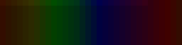
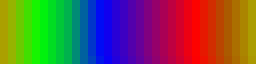
The following full-matrix RGB test frames show the simulator retaining colour gradations at low and high intensity after correcting the Wokwi brightness multiplier and moving the icon artwork to RGB888.
| Low-intensity RGB gradient | High-intensity RGB gradient |
|---|---|
 |
 |
Edit src/config.h, or override guarded values with PlatformIO build_flags.
| Setting | Default | Purpose |
|---|---|---|
DEFAULT_BRIGHTNESS_LEVEL |
9 | Startup value on the user-facing 1-10 scale |
MIN_BRIGHTNESS / MAX_BRIGHTNESS |
2 / 64 | Manual bounds sized for a regulated 5 V / 4 A source |
LED_MAX_MILLIAMPS |
4000 | FastLED estimated LED-current ceiling |
Wokwi MIN_BRIGHTNESS / MAX_BRIGHTNESS |
26 / 255 | Simulation-only range preserving visible RGB gradients |
DISPLAY_REFRESH_MS |
33 | Intended display refresh interval |
RTC_POLL_MS |
1000 | RTC cache refresh |
SENSOR_POLL_MS |
5000 | BME280 cache refresh |
CAROUSEL_SHORT_DELAY_MS / CAROUSEL_LONG_DELAY_MS |
5000 / 7000 | Runtime carousel dwell times |
CLOCK_12H_FORMAT |
0 | Use 12-hour display when set to 1; default is 24-hour |
BTN_DEBOUNCE_MS |
50 | Button debounce |
BTN_LONG_PRESS_MS |
800 | Long-press threshold |
BTN_REPEAT_INTERVAL_MS |
150 | Held-button repeat interval |
SETUP_TIMEOUT_MS |
7000 | Save and leave setup after inactivity |
SETUP_FLASH_MS |
500 | Selected-field flash interval |
Optional compile-time features include FEATURE_BOOT_ANIMATION and the currently unimplemented/disabled FEATURE_AUTO_BRIGHTNESS hook.
This clock was inspired by the open-source AWTRIX 3 project and its approach to presenting compact information and colourful icons on an 8x32 pixel display. This repository is an independent implementation and does not contain AWTRIX source code.
According to the project author, the code and documentation in this repository were developed entirely through vibe coding with ChatGPT, using GPT-5.6 Sol in Light reasoning mode. Juanjov supplied the requirements, hardware decisions, visual direction, iterative feedback, and physical validation; ChatGPT generated and revised the implementation.
Repository and file timestamps show seven distinct development periods between 21 and 28 July 2026. Their observed spans, plus allowance for isolated sessions represented by only one saved file, support an estimated 12-18 hours of active vibe coding. This is an estimate rather than a time-sheet measurement. A reliable cumulative token count is unavailable because no complete token-usage ledger was exported with the project or its chat history.
- No display: verify external 5 V, common ground, DIN rather than DOUT, D6, data resistor, and matrix layout.
- Random colors or resets: improve the power supply, ground connection, decoupling, and data wiring; reduce brightness.
- RTC not found: check A4/A5, address
0x68, breakout power, and pull-ups. - Temperature shows N/A: check A4/A5 and power; firmware probes both
0x76and0x77. - Upload fails: confirm the serial port, USB-to-serial adapter wiring, shared ground, and automatic-reset/DTR connection for the Pro Mini.
- Garbled geometry: select the matrix wiring layout matching the physical panel.
Copyright (c) 2026 Juanjov (jvalver1).
This project is distributed under the permissive MIT License. It may be used, copied, modified, and redistributed—including commercially—provided that the copyright and license notices naming Juanjov are preserved. The license includes the standard warranty and liability disclaimer.